10 February 2018

SV3IC SK

Nikos in December 2017 (photo by SV3DVO)
A dear friend, Nikos SV3IC passed away on February 9th, 2018. I met Nikos for the first time in 1983, when he brought his new Yaesu FT-ONE to Zakynthos for the hams of the island to see it. I was a high school student then. When I moved to Patras to study Biology in 1984, I started working part time with Nikos - he built and maintained commercial radio networks. I learned a lot from him but most of all had the time of my life, laughing my head off with his jokes and pranks, involving everyone around him - myself not excluded, of course! He was very kindhearted and generous, a lively mind with a sharp wit and a mischievous, impish manner.
An expert CW operator, he could operate flawlessly at speeds which made me dizzy. Always defiant of  misfortunes, he never gave up on life - and his favorite pastime, smoking. Confined at home during his last years due to illness, he never lost his wit and to the last day remained active on ham radio talking to friends near and far. 

Thank you and farewell, Nikos.

28 November 2017

Bringing back the memories - restoring a Graetz tube radio

A heartbreaking sight...
Courage old chap! You'll make it!!
After a rather loooong hiatus, here I am back again! No semiconductor stuff this time, though! Let's go back in time (the late '50s) and resurrect a nice Graetz MW-SW tube radio! It was sent to me a couple of years ago to restore (along with a very interesting Marconiphone model which will appear in a future post) and this is the story of its coming back to life.
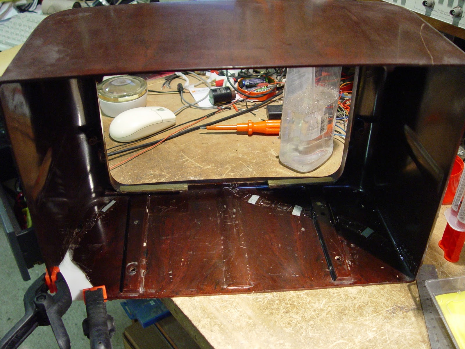
It was in rather heartbreaking conditions, all broken up, its nice bakelite casing in pieces (with some of them and the back cover missing) and everything covered up in years and years worth of grime and crud. (Click on the pictures for a larger version). One of the keys in front was missing, the power tranformer was burnt up, an IF can had a bad winding and - the worst - ALL of the RF coil pigtails at the underchassis were cut, probably by an industrious rodent which had left clear "marks" of its presence in several spots. Several other electrical problems became apparent during the restoration work, but they were not so serious.
RATS! Where are the coil pigtails?
Keeping detailed notes is a must.
Cleaning all that grimy mess of a chassis and case took a relatively long time and patience, but it was well worth it. When that task was complete, I started the electrical troubleshooting.
After ordering and installing a suitable new tranformer, I gradually checked and restored each stage. Surpisingly, most of the capacitors were OK! If memory serves, I found only a couple that had developed leakage. The reservoir electrolytic had more than its nominal capacitance and normal ESR.


Starting to look like a radio again...
It was during the testing of each component that I found that the IF can had a bad winding and opened it up to fix it. Fortunately, that proved easy. Finding where every RF coil should be connected on the bandswitch assembly was certainly the "funniest" part of the restoration! I also had to fit a new dial string, as the old one was badly frayed. After this was finally accomplished, the chassis was powered up and a voltage mesurement test showed some small remaining problems, which were quickly corrected. I found that the rectifier tube had gone bad and replaced it with silicon diodes in series with resistors, which were soldered on the tube socket lugs. That eased the burden on the transformer, too. It's very easy to remove them and fit a tube, if ever required. A loud hum could be heard when touching the grid of the audio amplifier tube, but no stations (of course) could yet be received.
To make a long story short, after restoring the function of every stage, I fully realigned the radio and it gradually came to life. First I aligned the IF, then the RF stages. Getting the dial indications to precisely correspond to the actual frequency is a very rewarding procedure. Stations started pouring in when I attached a wire antenna, and all of the wavebands became operational.
Putting the case back in one piece!
Alignment in progress...
Putting the broken bakelite case together was another challenge. I used epoxy glue and metal reinforcing clips to accomplish this. I formed, glued and painted a plexiglass sheet to put in place of a missing corner. Every brass part and insert of the front side was carefully cleaned, polished and protected with a thin acrylic coating. The speaker cloth was replaced with a new one. I was lucky to find a nice suitable replacement piece of cloth at a furniture shop. The case was finished up with gold paint because the original had faded with the years, and after several hours it was finally ready. I polished the bakelite with a silicone oil saturated cloth, which made it really shiny again and gave it a great colour and "depth". I made a complete back side cover out of thin plywood, as the original cover was lost (turns out I didn't take a photo of the cover).


The back side of the finished set.
Finished and singing!
Restoring an old tube radio is a very gratifying, educational and relaxing experience, especially when it's in the really bad shape the Graetz was delivered to me. It requires a lot of patience and  time, but in my opinion it's worth it. When you hear the first stations booming in after who knows how many years, it feels like you've given life back to a dear old friend. That particular smell emanating after the set warms up brings me back to my childhood, spending long night hours listening to my mother's Grundig 97WE (which still functions great!) to curious, noisy, wavering signals that arrived from the other side of the globe to my single wire antenna, strung out the window. Mysterious noises, warbles, twitters, whistles, strange music and serious, stentorean voices filled up my eager ears and made me wonder how it was ever possible for all those ethereal signals to travel so far and what each of them was. Listening to such signals coming from an old radio you've just restored to life is an indescribably joyful experience. Please don't throw those marvels of yesteryear away! If you don't want them, please try to find someone who appreciates them! They're a very important and beautiful piece of our technological history.
The Marconiphone radio restoration is another epic story, soon to be told!


26 April 2014

LDG AT-1000 autotuner acting strangely on some bands?

LDG autotuners are famous products worldwide, and for good reason: they are very well designed and built, providing a convenient solution when needed. There are very few complaints about them, as a quick Internet survey showed me. Why did I search, you say?
The other day a friend sent me an LDG AT-1000 that was acting up on some bands, failing to provide a match or even maximising SWR instead of minimising it, but working fairly well on other bands. He had been told it's the microcontroller's fault, and LDG even sent him a replacement chip (thumbs up for that kind of customer service), but the problem remained exactly the same with the new chip.
A quick check showed he was quite right: on 80, 40 and 30 meters the tuner was acting as a mismatcher, rather than a matcher. On 20 meters and higher bands, it worked rather well, although it seemed a bit "sluggish" (how's that for a scientific term?).
After examining the circuit in and out, I was sure that all of the relays, inductors and capacitors of the matching network were OK. I connected a dummy load at the output of the unit and saw that the autotuner indicated significant reflected power on 40 m, although there should have been none (I had it in the "bypass" position). "The SWR bridge circuit must be unbalanced", I thought - but why was it unbalanced on a specific frequency range? A Bruene circuit, if misadjusted,  behaves progressively worse as the frequency is raised - here, it was just the opposite! Nevertheless, I proceeded to balance the SWR bridge. For this, I cut the wire connecting the SWR circuit to the input of the tuner PCB, and connected a precision dummy load right after the bridge PCB with a very short piece of coax. I set an RF generator on 30 MHz and nulled the reflected power reading using the trimmer capacitor. Curiously, it was off by just a little. Hmmmmm...

Fig. 1. The bridge PCB in its original state.
After reconnecting everything back, I checked again on 40 meters with the dummy load at the output of the tuner, which was in the "bypass" position. There was a significant reflected power reading on the tuner's meter again - but NOT actual reflected power, as another SWR meter between the generator and the tuner showed me! Furthermore, on 20 meters there wasn't any reflected power indication on the tuner's meter with the same conditions! So something was clearly amiss with the bridge - but all of its components had checked out OK! Curiouser and curiouser!


Fig. 2. Look ma, no screws!
Fig. 3. The hi-tech insulators.
 After a considerable period of head-scratching, the light went on. The fact that the bridge was balanced on 30 MHz but not balanced on 7 MHz showed that at the lower frequency the RF currents must have been taking a detour. The only way I could visualise that happening, was through the grounding posts and grounding wire connected to the SWR meter PCB (Fig. 1 - click on the photos to enlarge). So I removed the two screws affixing the PCB to the posts, also disconnecting the wire this way. I checked again on 80 and 40 meters - and bingo! No reflected power indication any more! The bridge nulling remained excellent across 1.8 - 30 MHz. When I touched the PCB to the posts, the reflected power reading jumped up again. 
So, I modified the bridge structure by insulating the PCB from the grounding posts, as shown in Figs 2 and 3. I used a little square piece of thick paper at each post, hot-glued to the PCB and posts to accomplish my goal. I completely removed the grounding wire. After re-nulling the bridge (just to be sure), the tuner worked perfectly on all bands, with no abnormal readings at all. It even produced a 1:1 match feeding my 20 m quarter-wave ground plane at 80 m!
So, if your AT-1000 is horsing around on some bands, this trick may well work for you too. LDG might want to have a look into this matter and modify the design. For me it was yet another good reminder that RF currents, given half a chance, rarely pass from exactly where we would like them to!

Addendum: I just purchased a very nice LDG Z-817H tuner for my bicycle HF hamming during the summer! It has a different structure at our point of interest (the Bruene directional coupler is located on the main board) and a series of tests with various types of load conditions showed no tendencies for whimsical behavior. It successfully matched whatever I threw at it and had a nice time doing it. The directional coupler stays balanced throughout the operating range. Well done, LDG!

01 March 2014

Good news: YAESU has added the DC blocking capacitors at the IF filters of the FT-857D!


Fig. 1. The new FT-857D PCB.
Sometimes I think it's mothing short of a miracle that we can buy new technology products (like our transceivers) at VERY reasonable prices (not exactly so when I got into the hobby, 30 years ago - a handheld transceiver was a very expensive item in my country, it cost more than the monthly wages of a public employee).
In sharp (and delightful) contrast, recently I bought an Agilent E4406A Vector Signal Analyser,  an HP3586A Selective Level Meter and a Hagenuk Digiflex LAN Time Domain Reflectometer from the surplus market, at what must be a tiny fraction of their original cost! Mind you, the E4406A was about 45000 euros less than a decade ago! Long live companies like NOKIA (that's where my wonderful E4406A came from) and the ever-faster changing industry standards!
Fig. 2. The Serial Number.
But I digress... It seems that the nasty filter problem has caught the attention of the manufacturers! Tomi from Romania has sent me a photo of the PCB of the FT-857D he bought recently (Fig. 1 - click on the photos to enlarge), in which we can see that the DC blocking capacitors have been added! Thumbs up for Mama Yaesu! 
Maybe they do that for all their products now. I am sure other manufacturers have also taken steps to cure the nasty filter plague, but I haven't seen any concrete proof yet.
Tomi also sent me the serial number of his rig (Fig.2) - to save those that would like to add the capacitors in their recently-built rigs from the trouble! Thanks, Tomi!

05 November 2013

Great aerial video from the site of SV8S D-Star repeater in Zakynthos

Well, that's what they call a "bird's eye view", I guess! If you want to enjoy a great aerial view from the top of Skopos mountain in Zakynthos, a place that a lot of nice antennas call "home", use the link http://youtu.be/0Z1mXfpahfg (use "full screen"!). Mike, SV8KOM used his professional, high-tech, hex-rotor remotely controlled helicopter to record this video (and many others!). This is from where Stigma Radio 97.6 and Island FM 88.6  (in English) transmit their programs to the island and beyond! This is also the site of SV8S D-Star repeater (its antenna is located on the shorter mast, on the right of the one yours truly can be seen perched up on with his tools and stuff). It was a superb day to work on antennas! Oh, and I reeeeeally envy those birds!!

24 October 2013

Smoking is a no-no for your rig, too!

The photo (click to enlarge) shows the rather obvious effects of cigarette smoke on the keyboard membranes of a Kenwood TS-2000. The owner complained that the backlighting had gone very weak, so he suspected a circuit malfunction. Alas, his heavy smoking was the sole culprit.
The membrane soft plastic is normally semi-translucent whitish - not so after having been exposed to cigarette smoke for a while. It turned brown - and the worst part is, that this brown colouring is permanent! Obviously the stain gets into the plastic! This brown colouring acts as a filter for the green backlight, attenuating it greatly, to the point that it can be barely seen in complete darkness only. I have seen (and smelled!!) many rigs owned by smokers, it's definitely causing them serious cosmetic - and functional -  harm.
So, if you are a smoker, just imagine what kind of stuff the smoke is leaving behind in your poor lungs - perhaps quitting is the best option, both for you and your beloved rigs!

08 May 2013

Ants and aphids

You may have spotted a clue or two in this blog that I get most of my kicks from electronics and telecommunications. Nevertheless, having studied Biology at the University (fascinating science too), I frequently stop to admire the great work of Nature in all its diversity.
The other day I observed  what you can see in the photo (click on it to enlarge). The ants are seen "milking" the small dark-green aphids to get their honeydew (which they seem to greatly appreciate). The ants use their antennae to stimulate the aphids for this. They protect them from other insects that prey on them. This is called a "mutualistic relationship".

Now, you may wonder why I, being a radio amateur, like ants and other bugs. Easy: They use antennae, too!

11 December 2012

A proposed root cause for the "Withering Filters" phenomenon

Fig. 1 Photo by Jerzy,
SP6FPY. 
(Click to enlarge)
After having examined the failure mechanism of more than 100 ceramic filters that have succumbed to electromigration, I think I have collected enough data to propose a root cause for the phenomenon that has caused failure of a very large numbers of filters. I should gratefully thank the many fellow radio amateurs that have sent photos of their filters to me, adding to my database on the subject. Manufacturers might want to consider changing their production methods to avoid the chain of events that I propose that leads to this phenomenon.

So, let's look at the data I have collected and a proposed theory that explains the facts:

Fig. 2. Note the water droplets.
1) In all of the ceramic filters I have examined, there was a surprising quantity of water inside the plastic case (take a look at Figs 1, 2 and observe the signs of water presence on the elements and inside the black case, also the whitish flux residue on the case of the adjacent filter in Fig. 1, which shows that a quantity of water evaporated from that surface, leaving it behind). The water inside the case causes the filter to fail soon after the transceiver circuit applies DC voltage to the input, and mainly the output pins of the filter. The quantity of water is such, that can't be attributed to a filter manufacturing flaw: it's just too much. I can't imagine that the filter manufacturers would have ignored it. Also, I haven't found water inside some new filters I have "dissected". So, there must be another reason for this quantity of water inside the filter.

2) Where does the water come from, if not from a filter manufacturing flaw? I think the answer lies with the newer technologies and materials used for the fabrication of populated printed circuit boards (PCBs). Briefly, the new methods of wave soldering with non-Pb solders extensively use organic acid (OA) fluxes. Those fluxes are removed from the PCBs after wave soldering by pressure rinsing with hot water. The rinsing process takes some time to complete.

3) I think that the water ingress can be explained thus. The rinsing process uses hot water (about 70 degrees Celsius), sometimes with ionic additives. This (as well as the previous soldering process) causes the (so far dry) air inside the plastic filter case to expand, creating positive pressure inside the filter case. This results in air escaping from inside the filter case, as the temperature softens the plastic case and compromises the (not so great to begin with) sealing at the bottom of the filter case.
When the PCB exits the rinsing process, water is held by affinity under the filter case, between the filter and the PCB surface. The filter starts cooling down, and this causes the pressure inside the filter to drop under the atmospheric pressure. This negative relative pressure tends to draw a small quantity of the water under the filter inside the filter case, through the very fine cracks at the filter case seals that the positive air pressure (when the filter was hot) created. The quantity of the water is some micrograms, but it's more than enough to cause trouble. The board is then dried, but the accident has already happened. The water is already inside the filter.

4) Once inside the filter, the water can't escape and remains trapped inside the case. Some of it condenses or moves on the filter plates, starting the electromigration process where the electric field (due to the externally applied voltage) reaches sufficient value. This most often occurs at the corners of the thin output ceramic plate (element) at the output of the filter, which is only about 0.35 mm thick. This leads to the failure of the filter after some time.

5) What might be a solution? A slight modification of the rinsing - drying process might help in avoiding this phenomenon.
If the PCB is dried IMMEDIATELY after exiting the rinsing chamber with pressurised HOT air, then the water might not get inside the filter case, as the pressure difference doesn't occur this way before the water has been removed from under the filter.
I have no further knowledge of the exact conditions used in any particular case, so the above proposal may not always apply. But each manufacturer could certainly review the method used and modify it accordingly, so as to avoid the conditions that drive water inside the filter case (and possibly inside other "sealed" components, such as miniature relays).

If someone with more knowledge of the PCB processing methods wishes to add (or correct!) something in the above, please send an e-mail to sv8ym@raag.org.

73 DE SV8YM

Addendum: The above suggest that if you repair (clean and dry thoroughly with hot air) or replace a filter that has gone bad through water ingress during the rinsing procedure with a brand new one that hasn't come in contact with water, you may not have problems in the long run, even if you don't also install DC-blocking capacitors. That is so because you need BOTH water AND a voltage gradient to start electromigration. A completely dry filter probably can withstand 7-8 V indefinitely (as experience with older rigs shows - the PCBs were washed with organic solvents a long time ago, in the paleolithic Pb era!).
 

08 October 2012

A scorching hot summer in Zante

No, the airplane in the first photo didn't get entangled in my antennas!   It flew over the house and literally rescued our property from going up in smoke, like the pine trees in the second photo, where the plane drops 6.5 tons of water on the rapidly approaching fire front, less than 100 meters from the house (click on the photos to enlarge them). It was the 28th of August, and had the firefighter planes not arrived for another 10 - 15 minutes, all bets would have been off. It was the second close call this year for us. Such scenes have been extremely commonplace in my island during the last 25 years.
It's a sad reality that a vast pine forest area has been burnt to the ground during the last years, depriving Zakynthos of one of its greatest assets. Unfortunately, the great damage to the flora and fauna of the island will take many years to mend (if ever!). The planes and the firefighters on the ground (among them several volunteer radio amateurs) have saved many homes and possibly lives. We owe them all a big "thanks", perhaps more so to the pilots, who perform extremely dangerous aerobatics to deliver their payload with pinpoint accuracy.

05 October 2012

The GaAsFETgate scandal in Zakynthos

Click on photo to enlarge.
GaAsFETs have really become ubiquitus in every situation one wants high gain and low noise figure in frequencies ranging from the low VHF to microwaves. The picture on the left is of a very popular transistor (although a bit dated now), the ATF 10136 from Agilent Technologies. The ceramic cap has been removed to take this photo (about 200X magnification). 
The chip is in the center, attached to the source strip. The diameter of the white ceramic material is about 1.5 mm. The drain is on the right and the gate on the left. Observe the thin gold wires that connect the chip to its carrier contacts (and to your circuits!). This particular transistor (from a low-noise 2-m preamp) had a cruel death: it was accidentally (and quite scandalously!) bombarded with high power on 144 MHz from the amplifier of an EME setup in a friend's station. The gate short-circuited to the source, and you may see that even the gold wires almost melted by the heavy current that destroyed the transistor (see the red arrow). Fortunately, nowadays those great transistors are fairly cheap to replace, and can be easily procured.  Thumbs up to Agilent (now Avago, and the other semiconductor manufacturers) that make our beloved toys!

03 October 2012

Does your IC-E92D have any loose screws?

"It's the loose screws in my head!"
The IC-E92D is a very well constructed handheld transceiver, with a really solid feel of quality. I bought mine in 2008, in order to wet my feet in the new D-Star ocean. I also have the external speaker - microphone adaptor, which I think makes the rig a lot more pleasant to use.
The transceiver performed flawlessly, no problems at all, up to a few days ago, when I noticed that when I keyed the transceiver in medium and high power output on UHF using the provided rubber antenna, the display backlight would consistently and magically turn itself on and strange beeps and noises would emanate from the external speaker. The phenomenon was absent in the low and super-low power settings, so I reasoned that some kind of RF intrusion into the logic circuits was to be blamed. Removing the external speaker/mic cables changed things a bit (only full power produced the strange effects), but the goblin was surely still there. A quick search on the Internet revealed that other users have also reported similar problems with the display going blank or even getting inverted (!), so I was not alone out there. 
But what had changed to produce those effects? I hadn't changed anyhthing, the rig functioned with exactly the same accessories from day one. So, it was logical to think that the reason was internal.
Before opening the case, I studied the service manual a bit. I observed that the screws holding the transceiver together also had another very important mission: (especially the top two) pressed the main printed circuit board grounding spring contacts on the chassis. So these (and of course the other internal screws) are cleverly forming RF-tight enclosures within the transceiver. Could it be that some of those screws had gone loose, compromising this important function?
So, to take a first shot at it, I proceeded to carefully tighten the six screws that hold the transceiver together (they are at the back side, two of them near the top and four of them under the battery - you have to remove the battery to see them). Indeed, they took about 1/4 turn to feel nicely tight again (BUT DON'T OVERDO IT WITH THAT SCREWDRIVER, PLEASE!).
I am happy to report that the problem vanished immediately. I loosened the screws a bit again to see if it would come back, but it didn't, obviously because the contacts were not disturbed enough this way. My theory is that the screws gradually become a bit loose with normal use and thermal cycling, making the shielding / grounding contacts unreliable and "leaky". A bit of tightening and everything is back to normal again. Perhaps some day I will also have to open the case and tighten the internal screws, too. If the problem doesn't go away by tightening the externally accessible screws (especially the two ones at the top), that's the next logical step. This reasoning may also hold for other transceivers with the same shielding method. I must say I have certainly seen a lot of strange problems in other modern VHF/UHF transceivers go away when I tighten the screws that hold the printed circuit boards on the cast aluminum chassis!! They have a tendency of coming loose, mainly due to thermal cycling action.
Enjoy your IC-E92D and see you on D-Star!

14 June 2012

Removing the filter case without desoldering it from the PCB

Desoldering the ceramic filters in order to fix them can be a tough proposition in many cases. So, I came up with a different way of removing the plastic case - without removing the filter from the PCB..
Take a look at the picture (it's from the repair of an TM-D710E). Using long nosed pliers, grab the filter case exactly as shown and, gently but firmly, pull the case by - very carefully! - rocking the pliers in the direction of the red double arrow (perpendicularly to the longitudinal axis of the filter). The case usually comes off relatively easily and the offending elements can then be easily inspected, removed and cleaned, restoring proper filter function. Be careful not to lose the bronze tensioner spring plate that (usually) comes off with the case. This method of case removal has worked every time for me (I have fixed more than 50 filters up to now), saving me considerable time and work. Of course, after repairing the filters, don't forget to add the DC blocking capacitor at the output side of each filter, so that you won't have to remove the filter case again!

***ADDENDUM: Carefully heating around the base of the filter case for a few seconds with a hot-air soldering gun set at about 200 degrees Celsius usually makes the case come off much more easily. I said "Carefully", please take note!

01 June 2012

Sorry, Baldur

A well-known and widely respected fellow radio amateur and DXer, Baldur, DJ6SI, was arrested for "spying" (!!!) and put through an ordeal by the incompetent and ignorant Greek "authorities" in Kos island yesterday. As a radio amateur, I would like to express my sympathy to Baldur and say how sorry I am for the unfortunate event... Sorry, Baldur.

07 April 2012

The ailing ALC of the venerable FT-ONE - a gooey story

I recently got to restore an FT-ONE to full working order.   This particular FT-ONE brought back memories from 25 years ago, as it used to belong to a good friend in whose shack I drooled all over it, as it was the "Yaesu flagship" of the mid-eighties. That friend sadly passed away a few years ago, and the rig, after staying idle in storage for some years, was bought by another friend who sent it to me to shape it up, as it was quite unusable.
After fixing several problems (among them xtal oscillators that didn't want to go where they were supposed to and also an obnoxious general case of acute screwdriveritis the rig had gone through) and proceeding to full alignment, I stumbled across a most peculiar problem: The ALC was acting up. Although I could balance the directional coupler on 28 MHz (as indicated in the service manual), and then I could complete the ALC alignment transmitting into a dummy load, after a few hours, when first switched on and put to TX, the rig had a very low RF output (10 - 20W) and showed a large SWR indication for no apparent reason (transmitting into a dummy load). If I went on transmitting a carrier for a minute or so, the power would slowly come up, but even then it never reached more than 60 W or so on 1.85 MHz, and various other levels on the other bands - also, the ALC indication was fluctuating for no apparent reason.
Fig. 1 The gooey stuff!
I thoroughly checked the ALC board, suspecting a bad germanium diode - all checked out OK, as did all the transistors and trimpots on that board. Nothing there. I started suspecting some other part of the ALC feedback loop, but then my brain - in a rather rare epiphany - took in what my eyes had been seeing all along. Take a look at Fig. 1, click to enlarge.
Do you see the (kindly provided) red arrow? It points to a blob of some kind of gooey glue material intended to keep the directional coupler  toroid in place. I grabbed my ohm meter probes and placed them on two spots on the goo blob. Bingo! The goo was conductive! I read an indication of about 100 Kohm with the probes spaced a few millimeters. So the conductive goo was "leaking" RF current into the reflected power detector (D01), fooling the ALC circuit into believing that a serious SWR existed, so it promptly proceeded to reduce the output power (Yaesu calls this the APF function). Observe in the picture that the goo covers both the TX line (the bare thick wire through the toroid) and the winding ends on the right (where the enamel insulation had been removed).


Fig. 2 Off with the goo!
How to fix? Simple! Take a look at Fig. 2 (the "after" picture!). Using a thick needle, I scraped off as much of the brown goo as I could. I almost took it all off, it's hardened and breaks off in little chunks. I was careful not to scrape off the enamel insulation from the toroid windings.
After removing the goo, everything returned to normal. The ALC alignment went extra smoothly, and the power output is steady and OK on all bands. The high SWR protection now works perfectly.
This nasty goo has crossed my path for the second time: An old TS-440 that would impulsively unlock its PLL had plenty of the same goo on the VCO components. The resulting inter-component leakage was causing the PLL to unlock. It seems that with age this stuff oxidises and becomes conductive, upsetting sensitive circuits like VCOs and directional couplers. I wonder what brand name that goo was!!

15 February 2012

Summer, bicycle and ham radio - and "It's a cool, cool summer!"*...

Spring (and summer!) is ante portas, and sensitive guys like me just can't wait to hit the road to enjoy the season and pick daisies - getting on the air from my bicycle in the process! Nothing fancy - a garden variety 7 speed bicycle, the proper pannier with several big pockets, a rather modest collection of equipment, tools, mobile and wire antennas for HF/VHF/UHF, a battery, a solar panel and my trusty old FT-817, ready to give me me a lot of fun hours - and some much needed exercise, too! Also, I get to really observe many places I thought I knew - something you can never do cruising by in a car. The photo (from last year - click to enlarge) shows yours trully enjoying his coffee while operating on HF in front of an old, abandoned stone house in the vicinity of Agalas village, Zakynthos island. My antenna is a homemade whip for 20m, which doesn't show very clearly in this poor-quality cellphone picture. It's amazing, though, what you can do with such a simple setup on HF! More to come on the subject...
* I prefer cool summers to cruel ones!

13 February 2012

Noise for the boys

Fig. 1  Can you spot the missing part? (click to enlarge)
A few days ago, the digital TV broadcasts commenced (at long last) in my area, so I promptly installed a digital receiver and enjoyed perfect reception of those long awaited, crystal-clear TV signals. My initial joy vanished in a moment, though, when to my great dismay I found out that the digital receiver completely trashed my reception on HF with S9++ raucοus buzzing garbage all over the bands. I confirmed that the culprit was indeed the shiny new DVB receiver, by disconnecting it from the mains supply - then I proceeded to examine the entrails of that stinking rat. Not many surprises there - the usual, dirt-cheap switching power supply, where several corners have been brutally cut to keep the dreaded cost down. Take a look at the first picture (Fig. 1) - do you see anything missing? As the magnanimous host I am widely reputed to be, I have added a red arrow to help you figure out the answer - no frigging line filter at all, the one and only position for such a component had been jumpered in the most barbaric way. So the harmonics of the power oscillator that makes up the heart of the power supply are very efficiently radiated from the mains power lines - and I can assure you that those signals, although extra strong, don't carry any intelligence at all!

Fig. 2 The upgrade in place!
This is a very sad story indeed, causing serious grief to many unfortunate radio amateurs who suffer dreadfully degraded reception by the scores of big and small switching power supplies that infest the modern home (perhaps you have read my relevant QST 7/2004 article about "dirty", dirt-cheap computer switchers).
 Those power supplies are very cheap, but in this case cheap comes at a high price for radio enthusiasts who seek joy in the form of distant, low level signals. What's a young man (or lady) to do, then?
Other than replacing the offending switcher with a better quality one, which oftentimes isn't feasible at all, you could add the missing line filter elements yourself. Old computer power supplies will yield the necessary components for the tinkerer to lash-up a common mode line filter (Google it up and learn, don't expect everything on a platter from me!) - unless they're also rats themselves.
Take a look at Fig. 2 (click to enlarge), where the filter has been added to the rat, transforming it to something infinitely more tolerable. The toroid came from the line filter of a good, old computer switcher and worked fairly well, reducing in a single step the trash to about S2 - S3 worst case across the HF bands. (Someday I might get down to improving this even more.) The toroid has a bifilar winding, with each wire connected in series with each of the the mains conductors, just before they exit the case. 

Disclaimer: This mod requires working with dangerous mains voltages. Be cartain that you're up to it before tampering with a switching power supply, they definitely don't excuse ANY kind of mistake, and may immediately violently explode to show that fact!!

23 July 2011

The withering filters - adding a blocking capacitor when space is tight


Adding the DC blocking capacitors to protect the ceramic filters in your  rig may sometimes prove a bit difficult with the newer, extra small SMT components. Sometimes, there just isn't enough space or PCB trace length to accommodate the new part. In such cases, alternative methods might help, like the one in the photo (click to enlarge).
Here, the capacitor has been added only at the output pin of the filter (top right in the photo), because the output side of the filter is the most vulnerable (owing to the thinner ceramic resonator there). Due to the very small dimensions of the cicuit (the distance between the input and output pins of the filter in the photo is 8.3mm) there wasn't enough PCB trace length to comfortably add the capacitor by cutting the trace. So the solder was sucked out of the pin's plated-through hole, which left the pin standing in the center, unconnected. Then, the size 0603 capacitor was soldered at an angle, bridging the distance between the top of the filter's pin and the PCB trace. Problem solved, without PCB cutting (which may also sometimes prove dangerous to nearby SMT components)...Be sure to check whether the filter's pin actually stops making contact to the plated-rhrough hole, after you suck out the solder!

(The photo is from a President brand marine portable VHF tranceiver, that had gone completely "deaf" due to filter deterioration - after reviving the filter and adding the cap, it's back singing and dancing. The manufacturer [what a surprise!!] had omitted the DC blocking capacitors between the IF IC and the 2nd IF ceramic filter.)

23 June 2011

Dendrites, more dendrites!

The photos show another case of dendrite formation, although this time it's not in a mild, low voltage scenario (like in the infamous ceramic filter case).
That dendrite formed on one of my car's spark plugs when the ceramic insulation cracked and leakage occured, making the engine misfire and hiccup.
Observe the fractal nature of the dendrite, reminding of a lightning (which is exactly the same phenomenon at a much larger scale).
After I cleaned the ceramic surface with an abrasive disk and applied a suitable silicone oil with very high dielectric strength to the tiny crack, the spark plug worked very well for a few days until it was replaced.

Moral:     When dendrites grow
             like a thorny bush,
             your car starts going slow,
             you may well have to push...

(Click on the photos to see a larger version, the initial magnification was 25X and 200X, respectively).

10 February 2011

Addendum - The leaking Electrolytic Capacitor Plague and my TDS-460

The nagging thought that maybe, just maybe, there was more electrolyte hidden under one of the SMD ICs on the board gradually rose to an obsession. I had to see with my own eyes!
So I proceeded to remove U82, one of the ICs that had been affected, to take a look under the hood.The photo (click to enlarge) shows I had missed a spot, or rather three spots, where the electrolyte could potentially create trouble.
Fortunately, there weren't any signs of the electrolyte under the IC. The row of pins and soldered connections at the sides act somewhat as a barrier, and had prevented the electrolyte from creeping under the IC, holding it among the pins by affinity. Unfortunately, the electrolyte doesn't mind and does its frightful tricks there, too. There is no conformal coating immediately around the copper pads where the pins get soldered, and this facilitates the electrolyte getting under the coating exactly where it upsets things the most, creating parasitic conductance where there shouldn't be any. Scraping off and cleaning with IPA does the trick, a good measure of drying with hot air from an SMD soldering station and coating with a small quantity of acrylic varnish, applied with the tip of a fine painting brush (after the IC is back in place) ensures the best possible result.

And a word to the wise: Searching for information on the Web, I have seen that a lot of  fellows have had the same unpleasant experience with the Plague. In several fora it was recommended that the affected board should be washed under the tap with water. I am quite skeptical about that though, because the water could easily dissolve the dried-up residue of the electrolyte, which would then merrily wick itself deeper into the board wherever there isn't any conformal coating (immediately around the ICs pins, for example). Getting it out in that case might prove next to impossible.
When capacitor electrolyte contamination is the issue, removing it only at the affected spots by thoroughly scraping the residue and already damaged coating off the board (before applying any liquids), then thoroughly cleaning just that spot with a cotton swab soaked in isopropyl alcohol (IPA)  logically seems much safer. After drying with hot air (at about 140 degrees centigrade applied locally for about 5 - 10 minutes), one can seal the spot with acrylic varnish, removing the possibility of future moisture ingress.
A hasty cleaning action with the wrong means or method might make things a lot worse, so beware..!

30 January 2011

The Leaking Electrolytic Capacitor Plague and my Tek TDS-460

There are many good things in life, but bad ones tend to take more of humanity's time. There is compassion, love, science, understanding, but people spend most of their life - if not all of it - in greedy bellicose hunger, hating, believing in ghosts (holy or otherwise), and missing the - equally valid - other guy's perspective. The news every day provide ample proof.
Having put that off my chest, I had better now focus  my "elegant tapestry of quotations, musings, aphorisms, and autobiographical reflections" to the more mundane matter of  The Capacitor Plague, which, although completely unknown to the Medical Science, has caused many a frustrated consumer's tear to flow. In short, electrolyte leakage from bad (bad, bad) electrolytic capacitors destroys thousands of electronic devices every day, by corroding copper traces and creating parasitic conductivity on printed circuit boards. The plague doesn't discriminate and victims appear in every class of electronic devices. I have seen my car's ECU, personal computers, power supplies, test instruments, transceivers (and my friend's Stavros Sony ICF-80) die a gruesome death by the infamous Capacitor Plague.
In all godlike modesty, I have been able to resurrect most of the victims, save a few that were truly beyond redemption, as the time and cost to fix them was more than getting a new one. The latest unfortunate victim in my troubled experience was my beloved Tek TDS-460 digitising oscilloscope, a true work of four-channel art, which suddenly (and scaringly) started failing the self-test and showing erratic triggering (quite blasphemous for a prestigious Tek stallion). As the original SMD electrolytic capacitors, with a tarnished history of leaking, had been very wisely replaced with new ones before I acquired the instrument, I was almost certain that the malfunction couldn't be attributed to the electrolytics - although the symptoms - in an eerie way - pointed straight to that direction. Turns out that the Plague is like a time-bomb, and a very delayed one sometimes.

After thoroughly cleaning the (amazingly beautiful) acquisition board with isopropylic alcohol around the electrolytics, the symptoms went away (to my great joy), but only to come back to haunt me a couple of days later. I immediately repeated the cleaning and drying - same story. I replaced some of the caps in despair - nada. So I was clearly missing something. My trusty 4X Russian magnifying glass in hand, I started examining the PCB in detail around the electrolytics - and I finally spotted what you see in the pictures (click to enlarge), near the pins of U82 and U140. The discoloration was well concealed UNDER the conformal coating of the PCB and very hard to see, due to the light reflecting off the epoxy coating and the glare obscuring the surface under.
As there were no signs of electrolyte leakage from the new capacitors, the damage must have started with the old, leaky caps, and it took years to finally manifest itself as a malfunction of the instrument. The electrolyte had crawled under the conformal coating and gradually compromised the insulation, eventually disturbing trigger control potentials and making the self-test fail (it logged the error message: "trigComparatorTest, TRIGA status after trigger: exp(ected) = 1, act(ual) = 0).  The dried-up murderous electrolyte residue shows best in the second photo, of U82 (the first is of U140).
After scraping off the coating and affected spots under it with the point of a scalpel, the symptoms vanished, and this time I think it will be for good. I couldn't find any more such discolorations elsewhere on the board, but there's always the inaccessible area under the SMD  integrated circuits, so I shouldn't be unduly surprised if...!

Well, there's a nice thought to keep a test instrument lover twisting and turning in his bed at night...